Sensors in the refrigeration & industry
In this page you find sensors , which are helpful in your Refrigeration process.
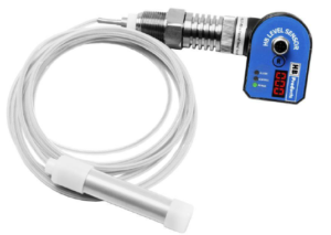
The HB L-t wire sensor is a very compact design. The only height for installation is 115 mm , due to split sensor design. The wire is teflon coated , therefore no risk on faulty alarm by contact with piping. suitable for marine applications.
A successful solution for level indication is the HBT the wired sensor , this sensor is easy to install and is suited with a separate electronically head and measurement sensor.
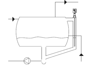
HBLT-wire is a capacitieve sensor for level measurement of NH3 refrigerant in industrial refrigeration systems.
The sensor has an output signal of 4-20 mA, which is proportional with 0 and 100%. Its output signal is 4 mA for an empty tank and 20 mA for a full tank.
It can be used as a level sensor, or it can be used as a combined level sensor and direct P-regulator of modulating valves e.g. level regulation in a chiller or plate heat exchanger
Adjusting to your situation:
HBLT-wire can be adjusted in length to the current application.
The sensor element consists of a 2mm steel wire as well as a Teflon tube.
Both parts are provided with a length of 4m and can be shortened with diagonal cutters or other pliers.
In cases where the customer wanted to configure the sensor, the target of a maximum of 5 minutes was achieved. There are only two parameters to set up in order to use the sensor for level measurement, which is a process that can easily be carried out in less than 5 minutes
To install: our recommendation is to install the sensor with a minimum of 50 mm from the bottom of the measuring pipe

Installing the HBT wire sensor in turbulent liquid bath ?
Use a guiding pipe – the sensor must be calibrated for the guidance pipe.

Technical details and features HBT-wire sensor | |
Connection | ¾ inch BSP or ¾ inch NPT |
Refrigerant | Designed for NH3 and HFC refrigerants : R22-R134A, R404A, R410A, R507 & R718 |
Suitable for Marine applications | The measuring wire is coated with Teflon, therefore no measuring fault due contact with tank nor pipe possible and suitable for sailing in rough water on vessels. |
Configuration | Easy configuration for refrigerant and length |
Split Design | The electronic part and measuring wire are separate for easy install and service |
Sensor | The wire is adjustable in length of 600 to 4000 mm. easy to calibrate. |
Dead zone | 0 mm |
Led display | Showing liquid level in percentage |
Alarm out put | 1 alarm can be set between 10 till 100% |
P-regulation of valve | The possibility for direct regulation of modulation valves, pilot valves of step motor valves |
HB L-T wire sensor | |
Adjustable length | yes |
Configuration of parameters | yes by PC |
Dead zone ( Bottom ) | 0 mm |
Installation height required | 115 mm |
Require preparation before installation | No , can be ordered at fixed length at no additional cost |
Required accessories for set up | Free software tool |
Time for configuration | Less than 5 min. |
Time for calibration | Time for calibration |
Require 0% calibration | No |
Require 100% calibration | No |
Comes standard with display | yes |
The HBLT-Wire sensor has been designed in a special way for easy installation and service.
Thus has been achieved by :
- No requirements for 0% or 100 % calibration
- No requirements for dead zone elimination
- A very low installation height (< 200 mm)
- Split design for easy troubleshooting
- Quick configuration of alarm outputs and sensor length
- The calibration can ordered by purchase by indication of the sensor length and refrigerant or configured easy on site.
Universal Liquid level sensor for al kinds of liquids also refrigerants

Was previous know as AKS 41

In the refrigeration industry this liquid level indicator is well-know his previous name was AKS41. Basic he is one on the most flexibel liquid level sensor, I personally worked with . In the refrigeration industry were we have liquids , which can easy transfer into gas and create a turbulent liquid bath this sensor is complete adjustable to your situation . Even for the refrigeration industry are the most common refrigerants pre-programmed .
Adjustable are the media, min/ max level and signal damping from 1- 120 seconds.
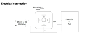
The sensor is designed as split sensor. powered by 24 VDC and out 4-20 mA.
There are two versions available : with local led indication bar and without.
Any questions contact us.

Code | Length | Thread connection |
T-28 | 280 mm | 1 inch BSPP |
T-50 | 500 mm | 1 inch BSPP |
T–80 | 800 mm | 1 inch BSPP |
T-100 | 1000 mm | 1 Inch BSPP |
T-120 | 1200 mm | 1 inch BSPP |
T-150 | 1500 mm | 1 inch BSPP |
T-170 | 1700 mm | 1 inch BSPP |
T-220 | 2200 mm | 1 inch BSPP |
T-300 | 3000 mm | 1 inch BSPP |

Code | Length | Thread connection |
T-6 | 6 inch | ¾ NPT |
T-8 | 8 inch | ¾ NPT |
T–12 | 12 inch | ¾ NPT |
T-15-3 | 15,3 inch | ¾ NPT |
T- 19-2 | 19,2 inch | ¾ NPT |
T-23-1 | 23,1 inch | ¾ NPT |
T-30 | 30 inch | ¾ NPT |
T-35 | 35 inch | ¾ NPT |
T-45 | 45 inch | ¾ NPT |
T-55 | 55 inch | ¾ NPT |
T-60 | 60 inch | ¾ NPT |
T-85 | 85 inch | ¾ NPT |
T-105 | 105 inch | ¾ NPT |
T-120 | 120 inch | ¾ NPT |
Approvals: | |
CE –approval | EN-61000-2 |
EMC Emission | EN61000-3-2 |
EMC Immunity | EN61000-4-2 |
GOST R | No 0903044 |
Technical Data: | |
Voltage | 24 V AC/DC ±10% |
Analog output | 4-20 mA |
Led indication level | Led bar ( as option ) |
Calibration | Calibration button / led indication |
Alarm output | No |
Enclosure protection class | IP65 |
Max load resistance | 500 Ω |
Ambient temperature | -30 / +50°C |
Medium temperature | -60/ +80 °C |
Max pressure | 100 bar |
Vibrations | IEC 68-2-6 (4g) |
Specified cable | 3 x 0,34 mm2 |
Cable glands | PG7/m8 |
Plug connection | DIN 43650- 4 pins |
Cable resistance | 500 Ω/km |
Tread connection | ¾ inch NPT of 1 inch BSPP |
Material mechanical parts | AISI304/ PTFE/ thread AISI 303 |
Material –electronic parts | Nylon 6 (PA) |
Material enclose | Coated cast alluminium |

To Select the correct refrigerant follow the instructions:
Important Note : the calibration push pushbutton must be activated , before the supply power is connected- otherwise the signal damping will be changed.
Please follow the instructions .
Step 1: To get in the refrigeration selection mode – push the calibration pushbutton and keep it pressed while connection the 24V/ plug –than release the pushbutton.
Step 2: After releasing the push calibration button -observe the present refrigerant setting and measure the current setting by the out-put signal 4- 20 mA – all refrigerants come in the sequence ( the factory setting is NH3- R717 or R718)
Refrigerant | Indication of the green led | Out signal ~ |
R717- R718 ( Factory setting ) | 1 Flash | 5 mA |
R22/R507 | 2 Flashes | 6 mA |
R404A | 3 Flashes | 7 mA |
R134A | 4 Flashes | 8 mA |
R744 | 5 Flashes | 9 mA |
Step 3:
Activate the calibration button to select the correct refrigerant.
Step 4:
When the current corresponds to the required refrigerant, wait for 10 seconds until the green led is constant illuminate ( not flashing). This indicates that the required refrigerant has been selected.
Step 5:
To leave the setting mode isolate the voltage to the level transmitter by disconnection the plug from the transmitter.
Go through step 1 , 2 and 5 if you wish to control the setting.
Signal Damping:
The factory setting is 15 seconds. The damping setting can be changed by activating the callibration switch over a range of 1 till 120 seconds. The setting can be changed wihle the system is in operation.
Procedure for singnal damping:
Step 1 :
Connect the power supply
Step 2:
Push the calibration button or each second by which you what ti incrrease the damping.
or example; 1 push = 1 second, 2pushes = 2 seconds ….. 120 pushes = 120 seconds , 121 pushes = 120 seconds.
10 seconds after the last push, the value will be saved in the memory and the green led will start flashing again. After 10 seconds, a further push will start 1 second signal damping again.( if the damping is too high restart the procedure from step 1 again.
Min and max level setting
Calibration is required if:
- The default setting does not fit and the min/ max calibration points have to be adjusted. The factory setting is 0% ( free of liquid – 4 mA – Max level 100% -20 mA – the max / min points can be set to any value.
- The liquid level sensor is used in liquid , which is not covered in pre-settings
- The electronic head is replaced on a existing rod
Adjusting the min level :
- Bring the liquid level to the desired minimum level.
- Press the calibration pushbutton and keep it activated for approx 5 seconds, until the green led stops flashing.
- Activate, within 10 seconds , the calibration button once.
The green led is illuminating for few seconds and then start flashing. The output is 4 mA and the sensor is in normal operation.
Adjusting the max. level
- Bring the liquid to the desired maximum level.
- Press the calibration button for approx 5 seconds, until the green led stops flashing.
- Activate, within 10 seconds the calibration button two times with 1 second in between.
The green led is illuminate for few seconds and then starts flashing. The out put is 20 mA and the sensor is on normal operation.
Important note: if the calibration button is not activated within 10 seconds, the calibration mode will be left and the sensor is in normal operation.
Reset to factory settings
The sensor can always be reset to factory settings,by:
- Press the calibration button and keep it activated for 20 seconds until the green led starts flashing.
- Release the calibration button.
When the red les start flashing , the reset to factory settings is completed
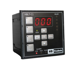
The HBLT-C1 is a easy controller to handle – for all kind of liquids. Check the posibilties in the manual. very complete controller for a reseamble price level.
Any questions contact us.

